The Horizontal Blank is part of each
scan-line, so we do not need to worry about generating it.
Everything else is up to us. We need to generate a sync signal
over 3 scan lines, after which we have 37 scan lines worth of
machine cycles (37 scan lines * 76 machine cycles per scan
line = 2812 machine cycles before the TV picture) before we
tell the TIA to "Turn on" the image output. Now we need to
update the TIA so each of the 192 scan-lines that comprise the
visible portion of the display are updated to what they are
supposed to (14,592 machine cycles). Once that is done we
"Turn off" the image output, now we have 30 scan-lines (2,280
machine cycles) before we start all over again.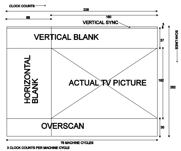
The quality of the picture depends oh how efficient one can write code for the TIA, as the years went by, people3 started writing more advanced displays:
 Combat (1977) |
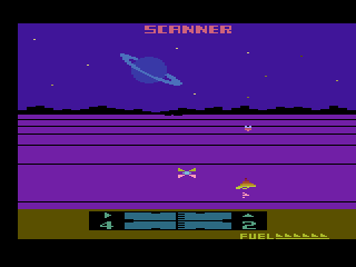 Solaris (1986) |
| VSYNC |
|
|||||||||
| VBLANK |
|
|||||||||
| WSYNC (wait for sync) |
Data bits not used (just write to it) |
To provide additional resources, the system is equipped with the RIOT chip (Ram, Input, Output, Timer)
- a programmable timer
- 128 bytes of ram
- two 8 bit parallel I/O ports
The timer can be set into 1 of 4 modes:
| Cycles Per interval |
Register Name |
| Count down every cycle | TIM1T |
| Count down every 8 cycles | TIM8T |
| Count down every 64 cycles | TIM64T |
| count down every 1024 cycles | T1024T |
128 bytes of ram:
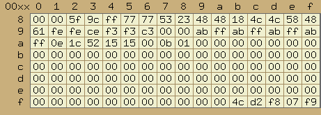 |
The entire 128 bytes of RAM the stock
system has. This can be extended with additional Ram
chips located withing the game cartridge. The extended ram is usually another 128 byte ram chips. But configurations that allow 256 byte and more exist, however these are more rare. The vast majority of games only used the on board 128 bytes. |
And then there is the Starpath Supercharger. Adds 6k of ram and games are loaded off audio cassette's.
My own Atari 2600 game: Diamond Drop
Online Emulator: Javatari